If you're confused or you'd like to suggest improvements, please email me at contact@leaphand.com."
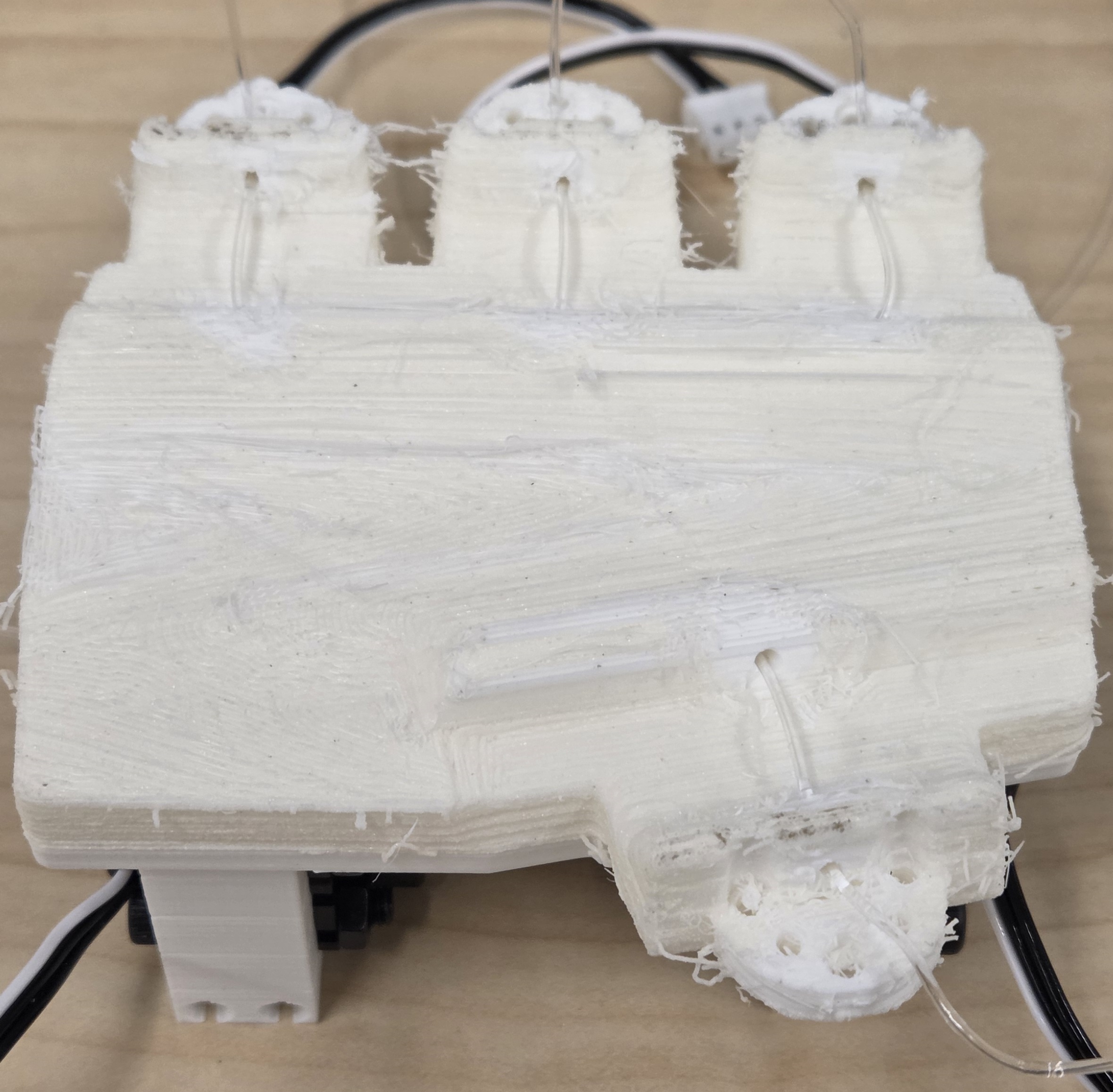
Prepare 3D printed parts:
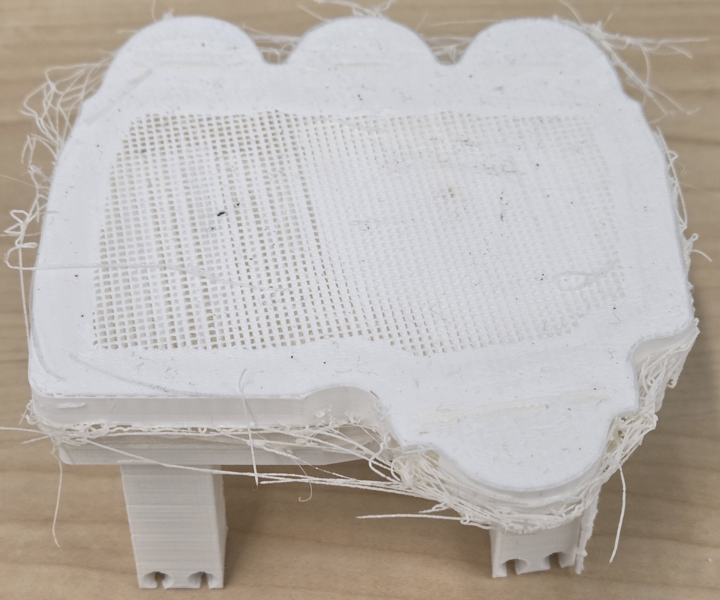
- PLA support is used during the printing process.
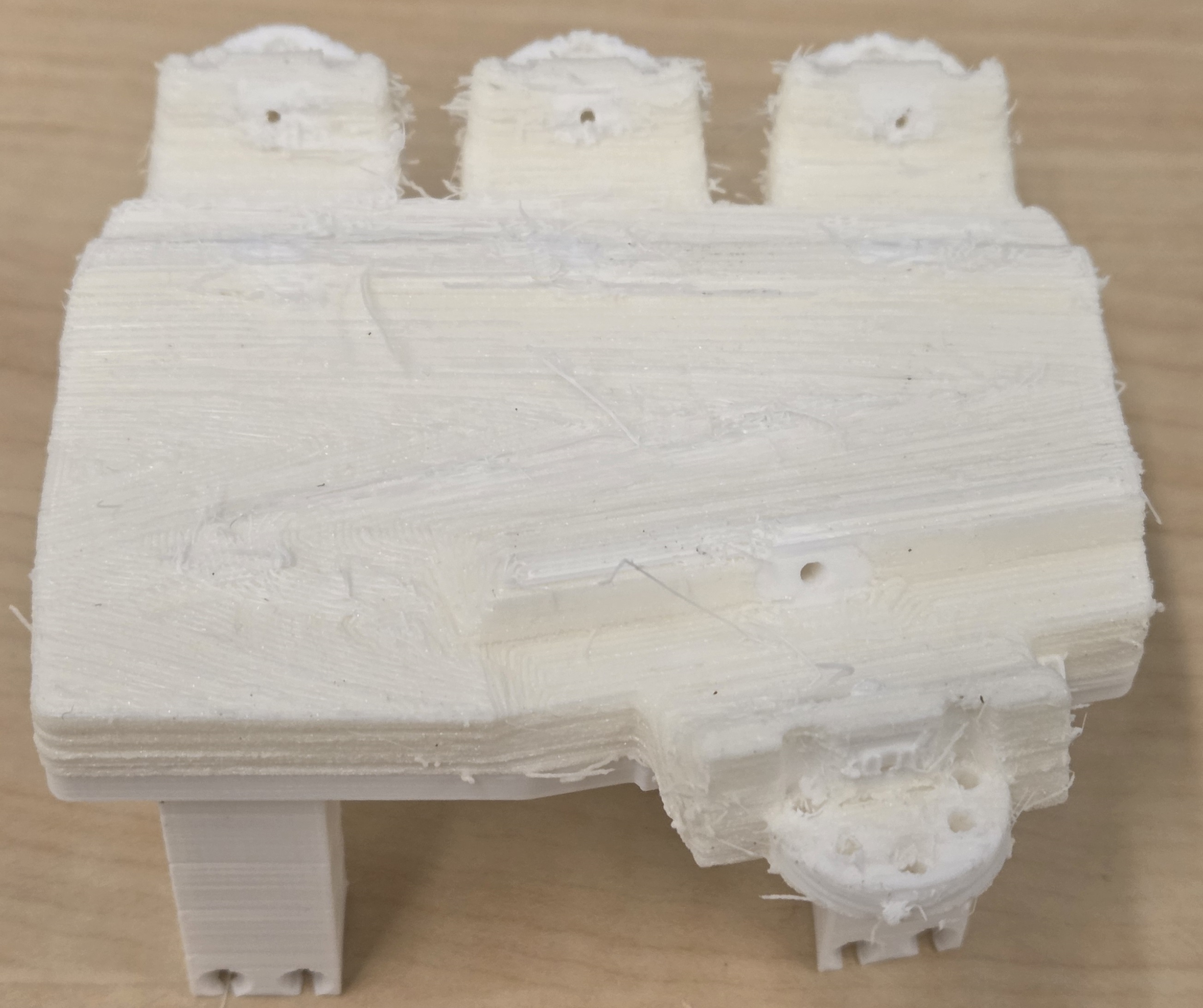
- After printing, gently remove the PLA from the TPU using a small cutter or pliers.
- For the four fingers, pull support material from the fingertip toward the MCP base. Avoid pulling top-to-bottom, as it may cause layer separation.
- Clear any remaining support from the tendon hole entry points on especially the palm. Use a small drill bit if needed (internal channels are typically already clear).
- Use a small drill bit to clear the M2 motor mounting holes on the palm.
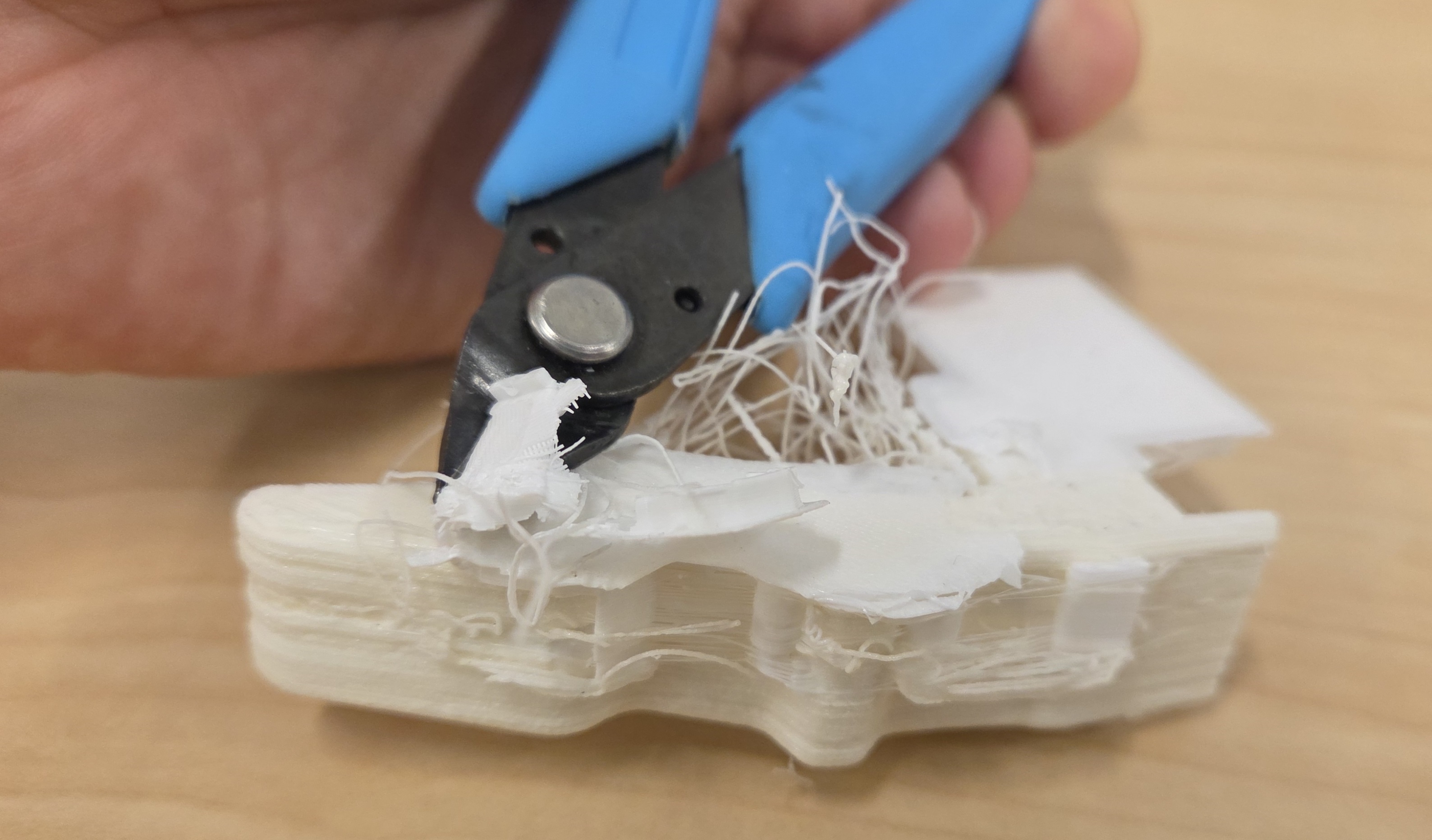
Tip: Take your time and proceed carefully to avoid damaging the TPU skin!
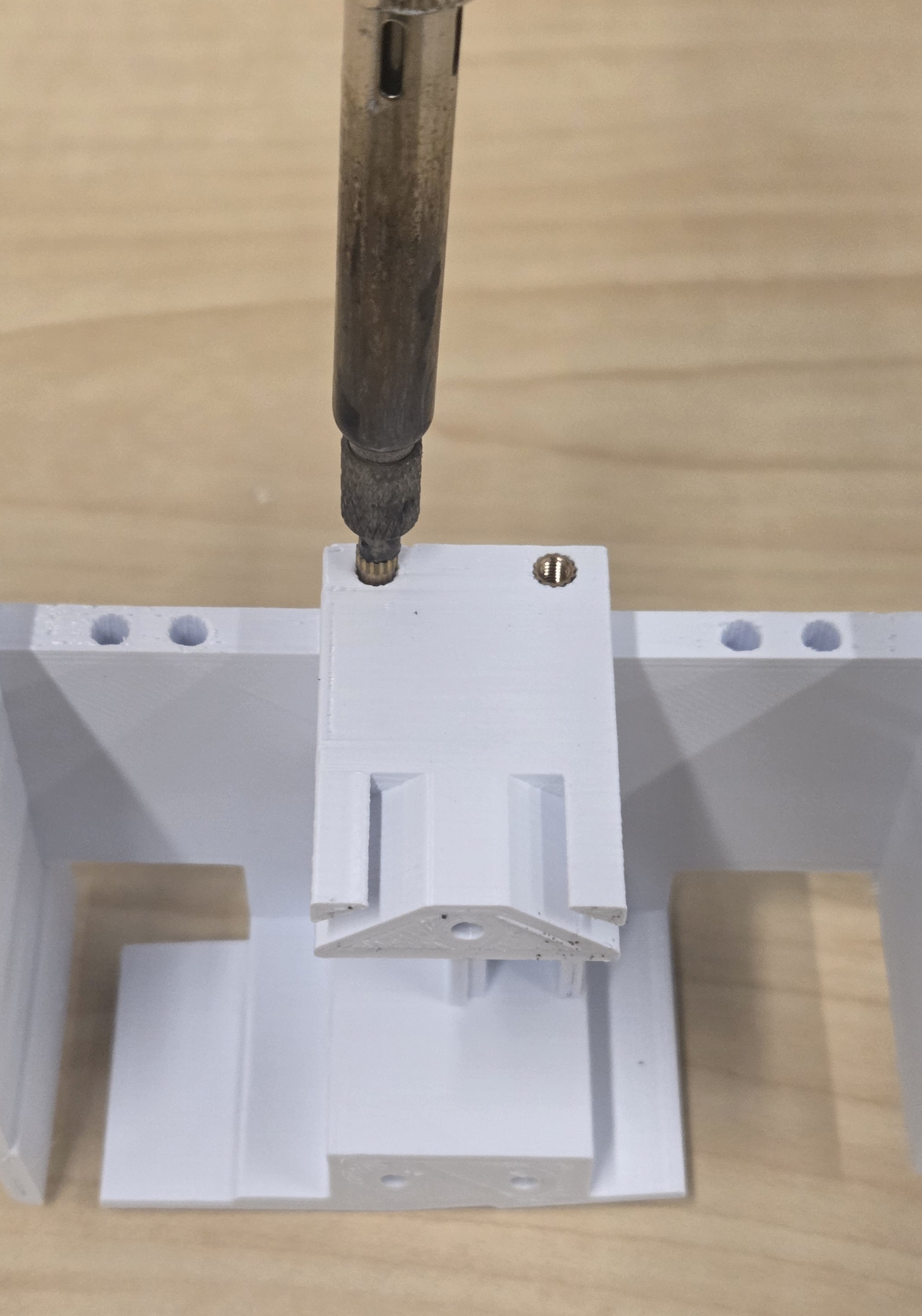
Brass inserts help screws go into the 3D printed plastic more easily and hold securely. To use them:
- Put a soldering iron tip that fits the insert well.
- Heat the soldering iron to around 240C
- Press the brass insert carefully and steadily into the hole.
Palm Top:
- Insert 12x M2.5 6mm brass inserts around the perimeter holes of the palm top.
- Insert as many M2.5 4mm brass inserts into the top of the palm top to hold your USB board and optional LEAP Power board.
Palm:
- Optionally, insert three M2.5x4mm brass inserts into the main palm holes along the bottom edges. These screws may not be necessary, depending on how secure you need the palm.
Wrist Mount:
(Do these wrist parts only if you are using the wrist mount)
-
Insert four M2.5 x 5mm or M2.5 x 4mm brass inserts into the flat base to mount the USB board.
Tip: Inserting them from the back may be easier.
You should put inserts under the cover (side without the thumb) if you are using LEAP Power. If you aren't, I recommend putting inserts under the thumb to give more space for the cables. - Insert 2x M2.5 4mm brass inserts into the knub next to the arm to hold the lid on.
Wrist Lid:
- Insert 2x M2.5 4mm brass inserts into the side to hold it in place.
Fingers
- Insert 2x M2 6mm or 8mm brass inserts into the finger holes on the bottom of each finger.
Tip:If a few of the inserts don't hold, that's okay—there's some built-in redundancy, so not every single one is required.
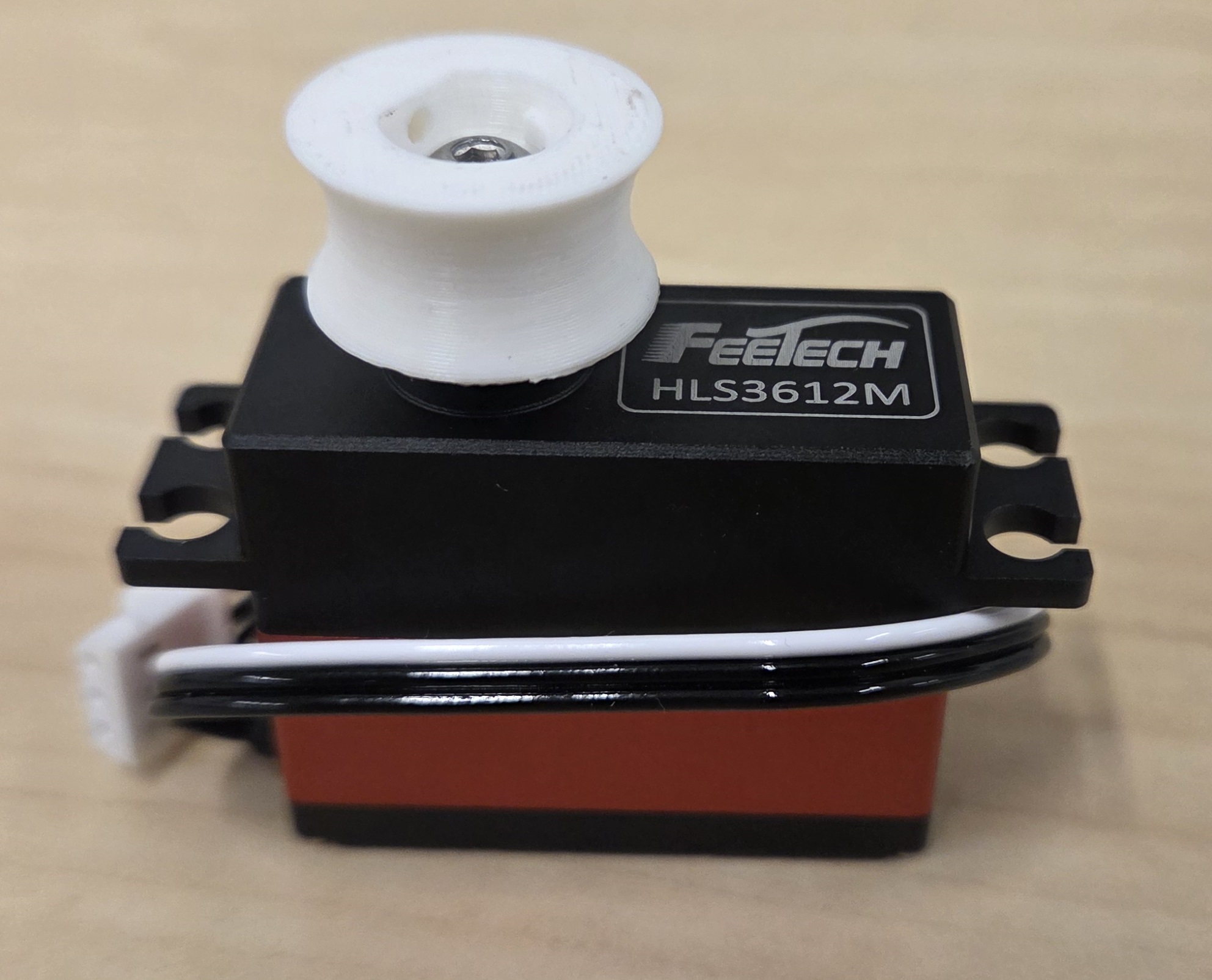
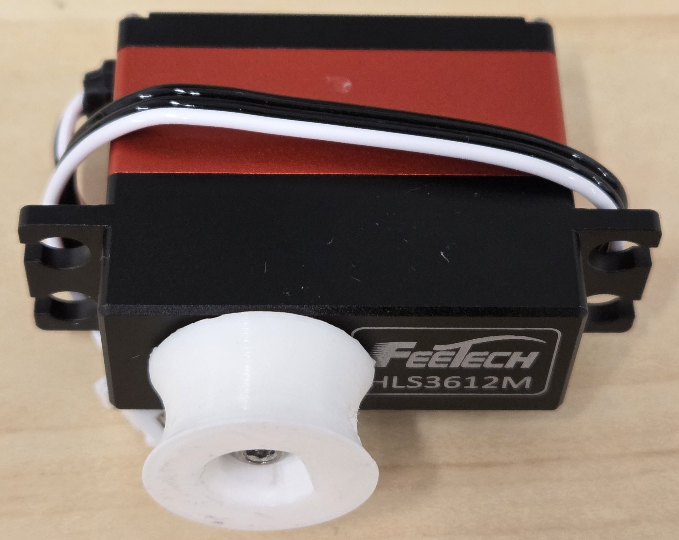
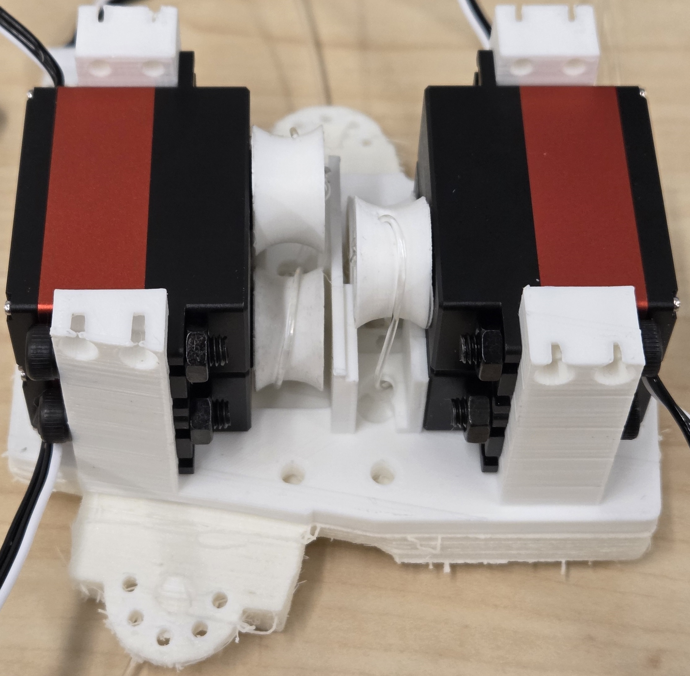
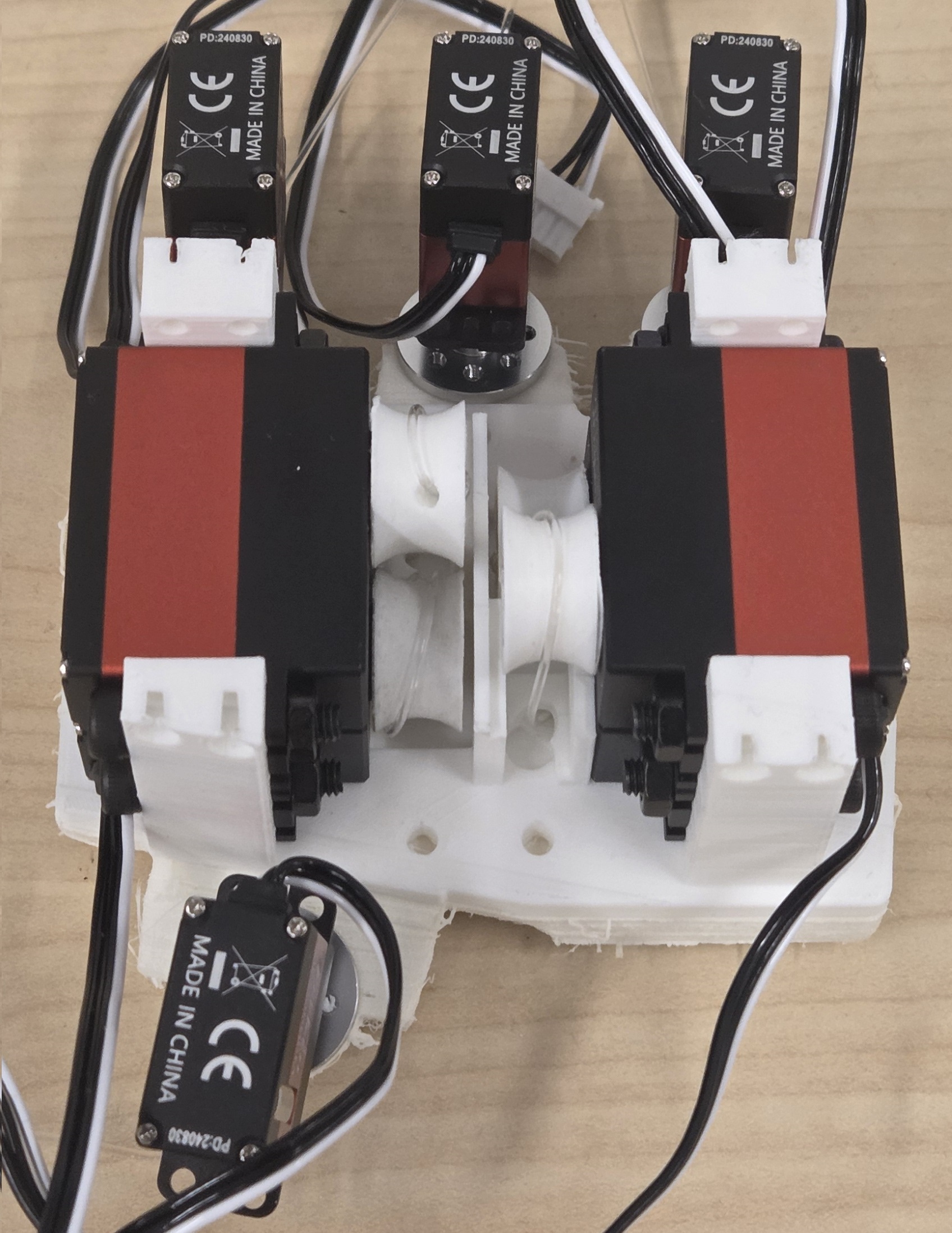
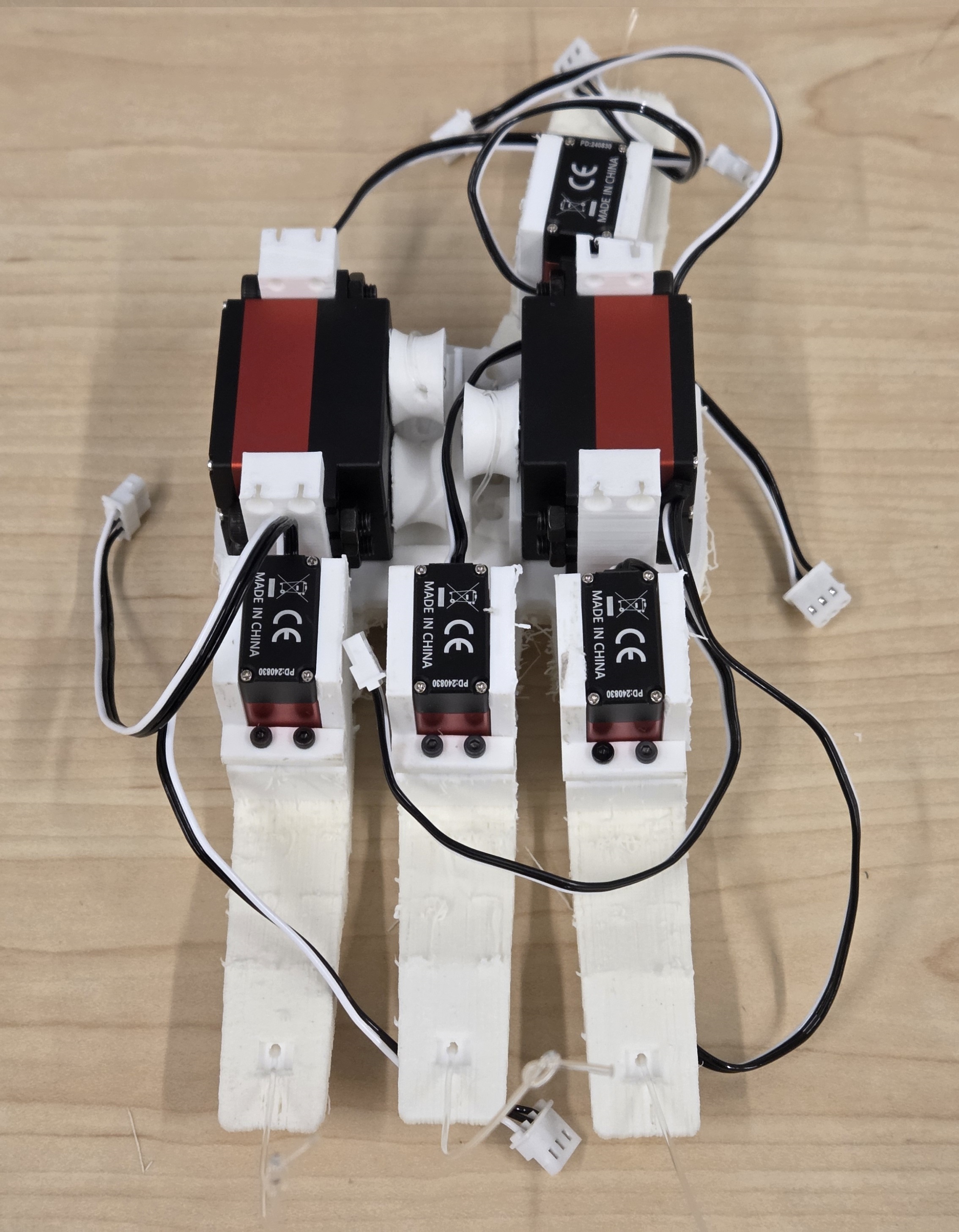
Prepare Curl Motors and Tendons
- Make sure the pulley horn printed correctly with the 0.2mm nozzle — it should have a clear jagged pattern that matches the horn design.
- Gently slide the pulley teeth around the motor horn until they begin to engage. It may be too tight to push fully by hand, but should start to line up.
- Use a M3 8mm buttonhead screw and screw it in through the pulley into the horn until the screw cannot easily turn becauase of the pulley.
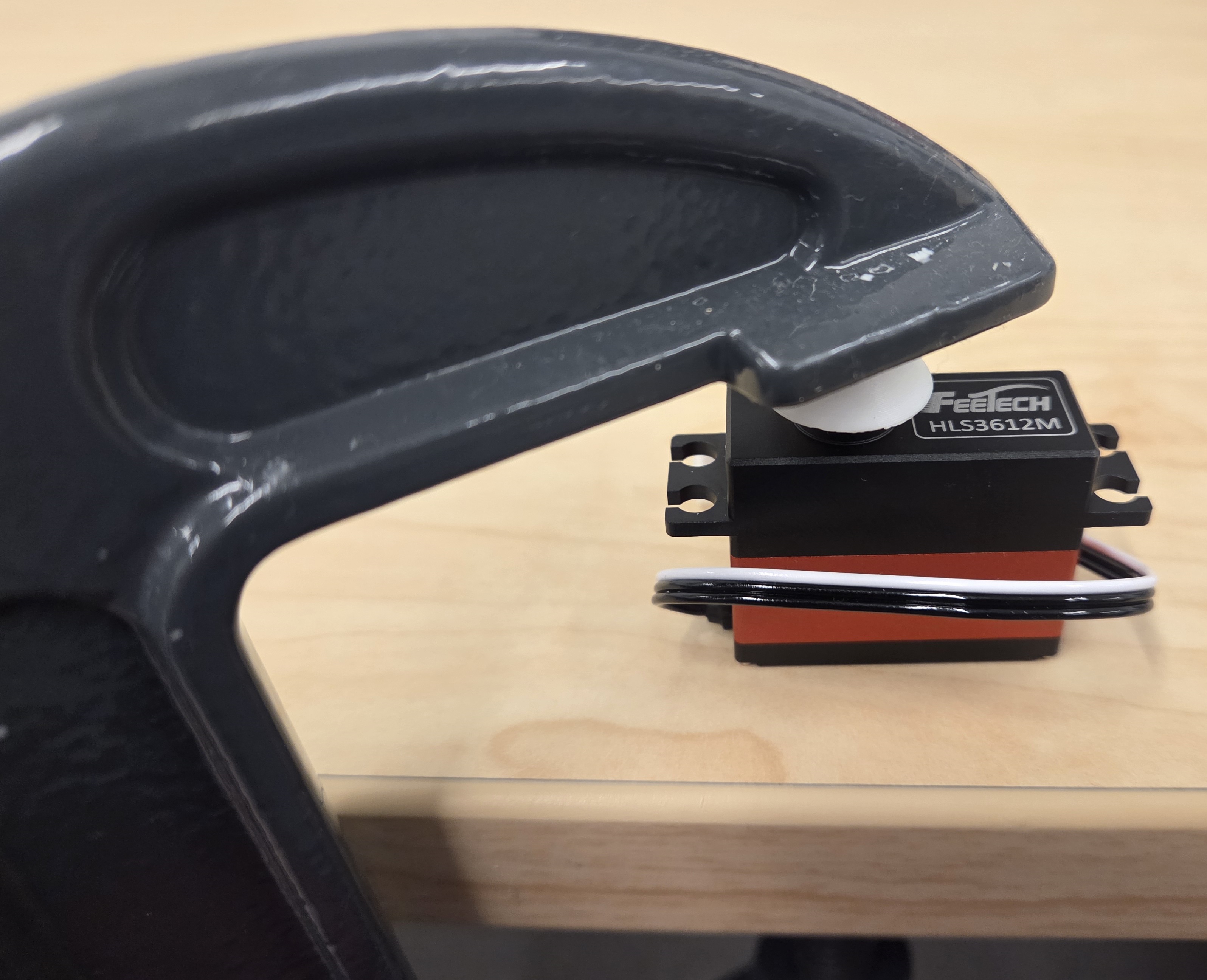
- Place a clamp around your desk, put the motor on top with the pulley facing up, and then carefully push down on the face of the pulley using the clamp.
- Repeat clamping and tightening the screw gradually until the pulley sits flush against the motor—be careful that it's flush, but it should not be rubbing.
- Unspool some of the fishing line, roughly 4x the length of the finger, and cut it.
- Tie a normal knot on one end. Put that knotted end through the small hole in the pulley so the knot sits securely inside the center of it. Pull it hard to make sure the knot does not slip out. Cut the excess fishing line after the knot.

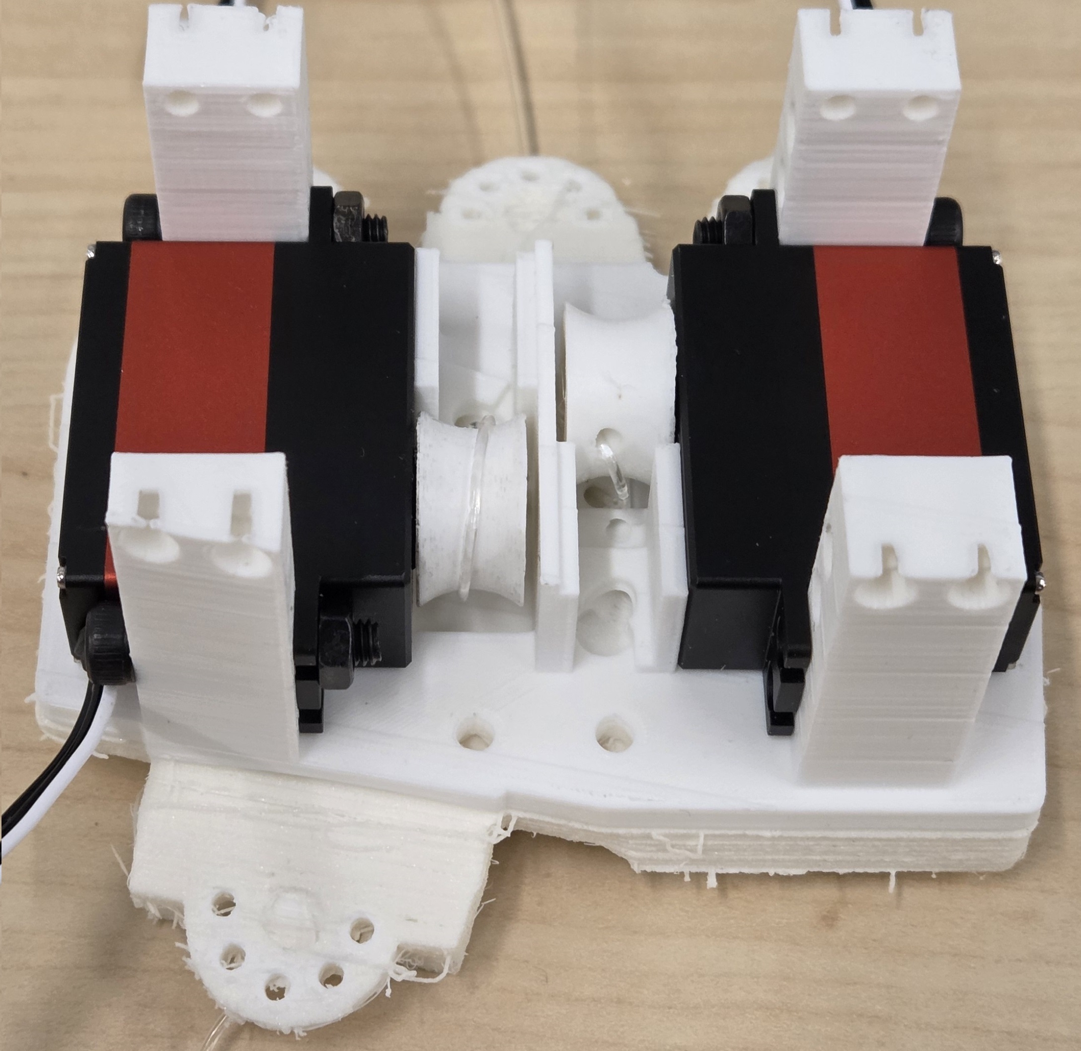
- Find an open slot, thread the tendon through the corresponding hole in the palm, and pull it all the way through the palm and through the base MCP joint.
- Carefully place the motor into the corresponding slot, making sure not to pinch the tendon.
- Secure each motor using 3x M4 20mm screws and 3x M4 nuts. The head of the screw should be facing outwards so it is easy to tighten. (Note: only one screw can fit on the cable side—be careful not to crush the cable.)
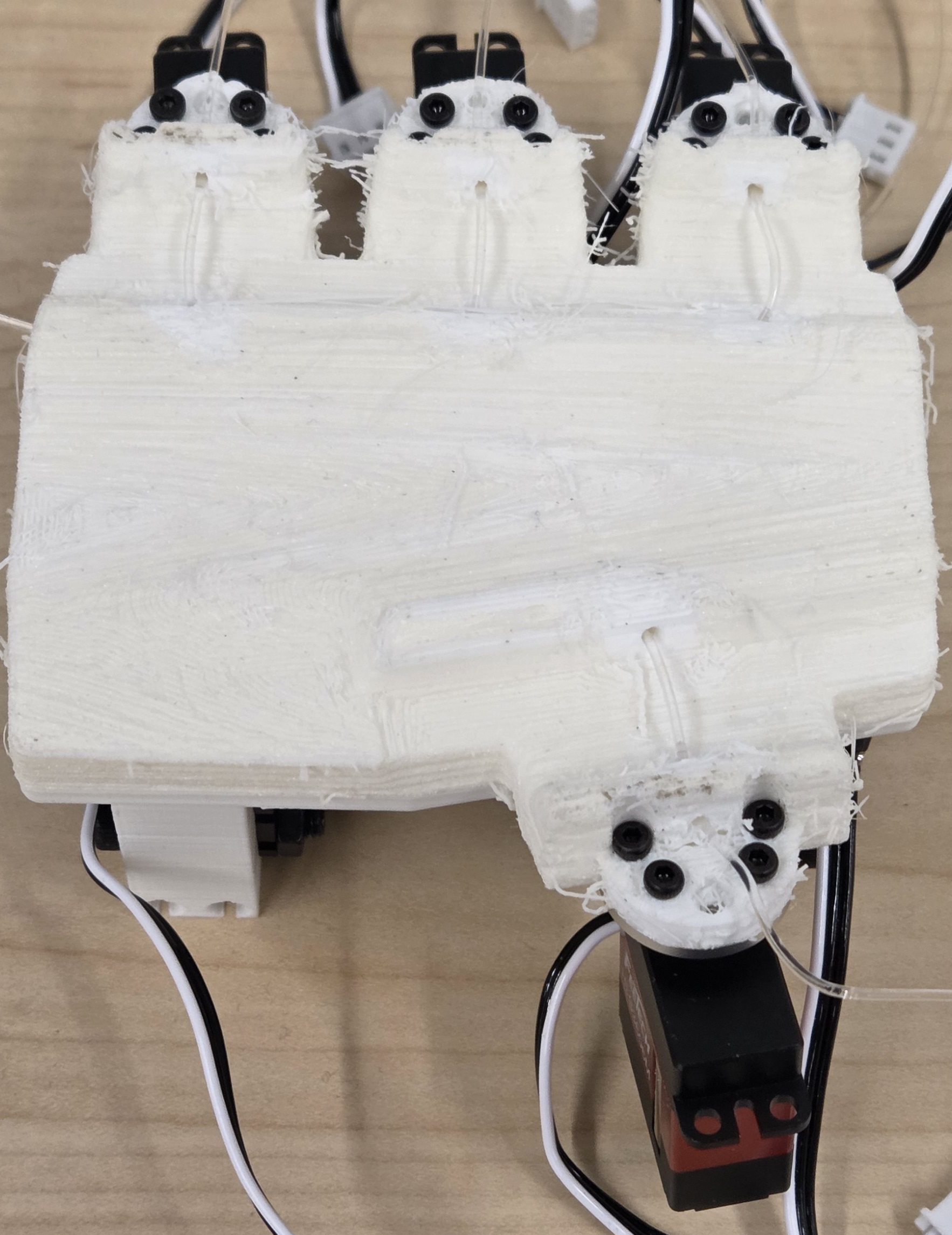
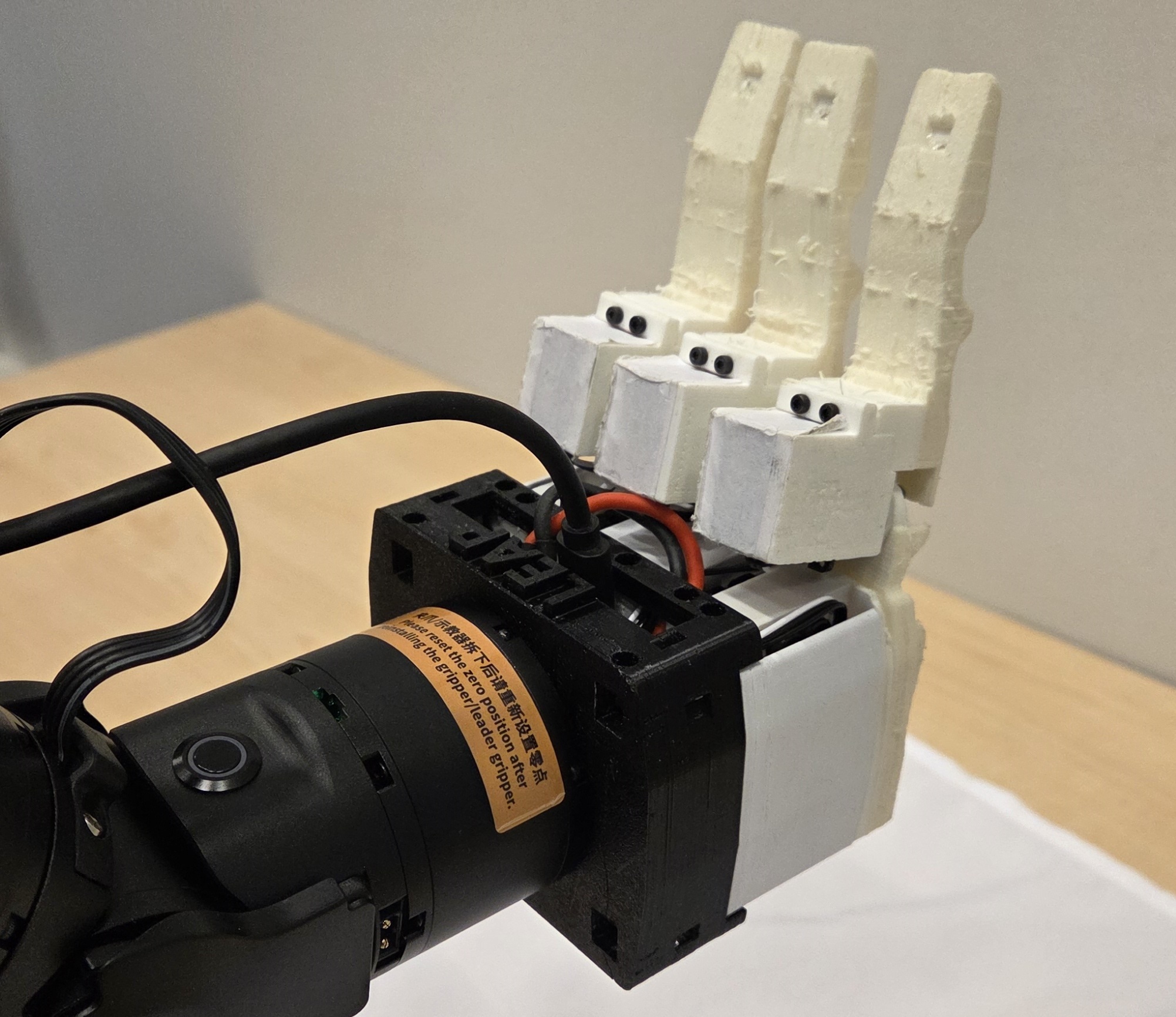
Attaching MCP Side Motors to Palm
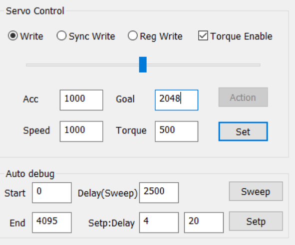
We must power up the MCP side motor to figure out its home pose.
I recommend you temporarily wire the motor to the USB board and the optional LEAP Power board as shown using 7.4v. Then you can set the motor to the home position of 2048 either using our provided script or the Feetech GUI.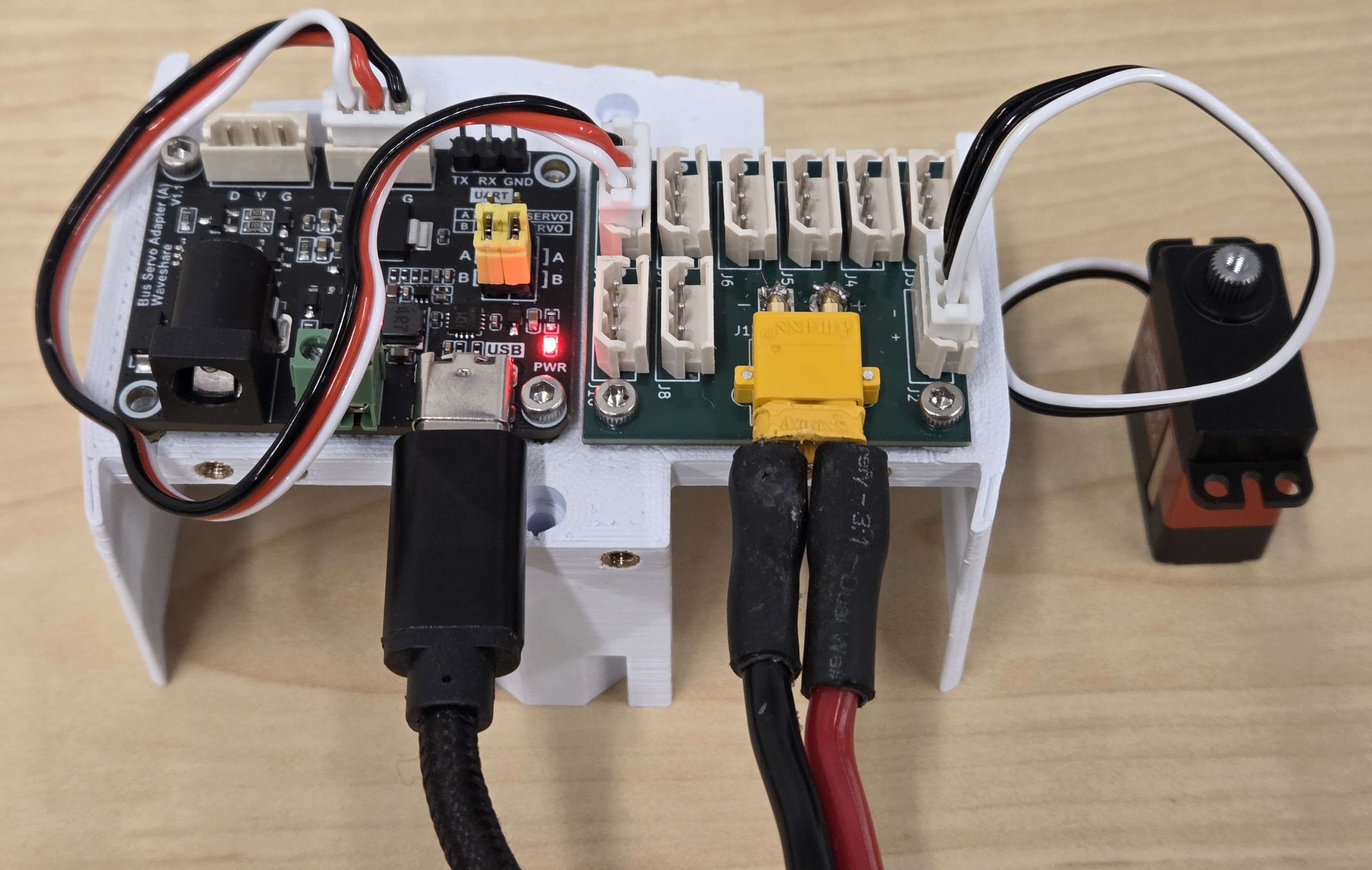
For the wrist mount option, you should not mount the boards here.
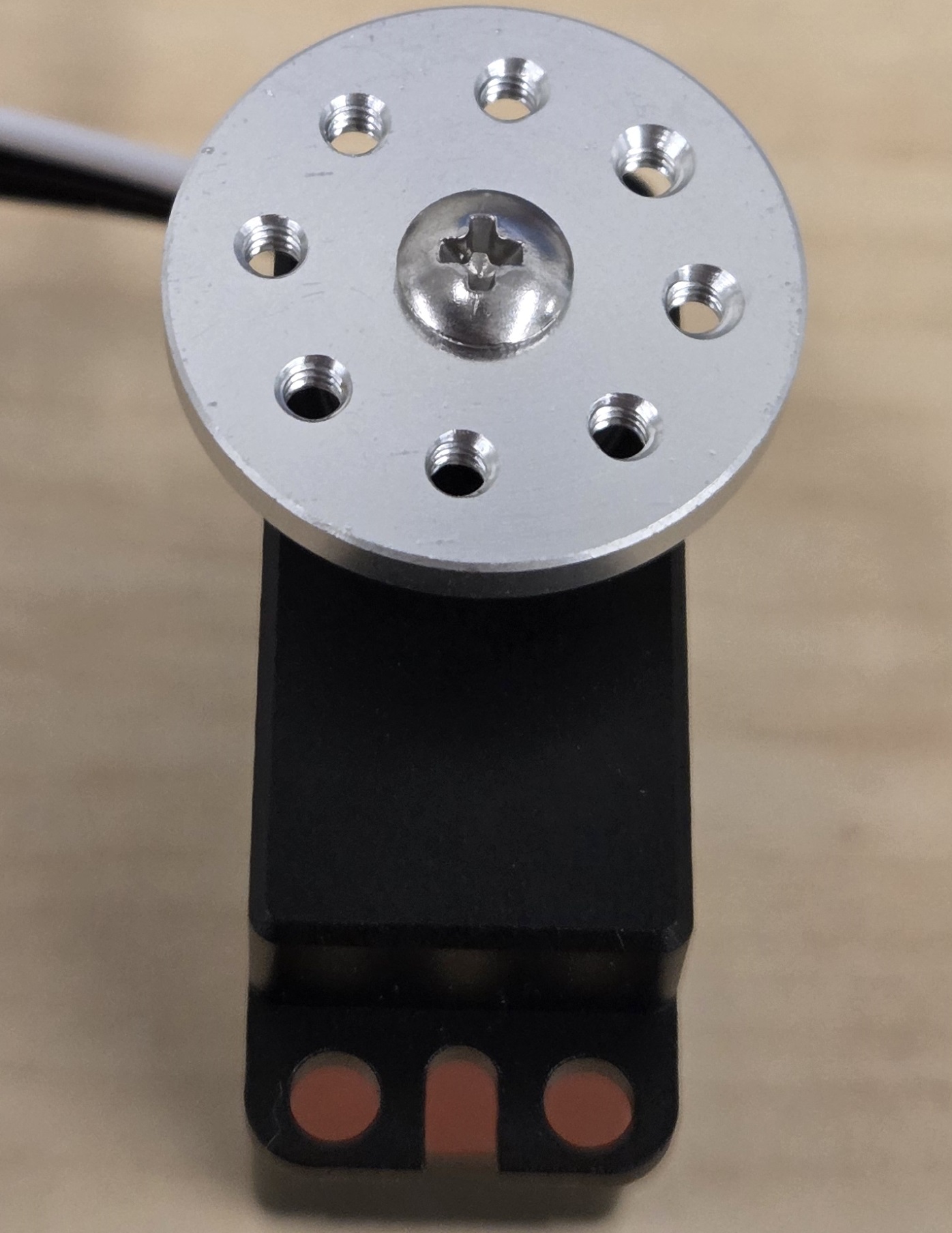
Attach Horn to Motor
- While the motor is powered, align the horn so that its holes are roughly aligned with the top, bottom, left, and right of the motor. Unfortunately, it won't be perfectly precise, but this will be corrected later in software.
- Press the horn down onto the servo and use the Feetech supplied M2.3x5mm phillips head screw to tighten the horn.
Attach Horn to Palm
- Use four M2x6mm screws to fasten the MCP-side motor to the underside of the palm finger joint. You may unplug the motor if needed, but be careful not to rotate the horn.
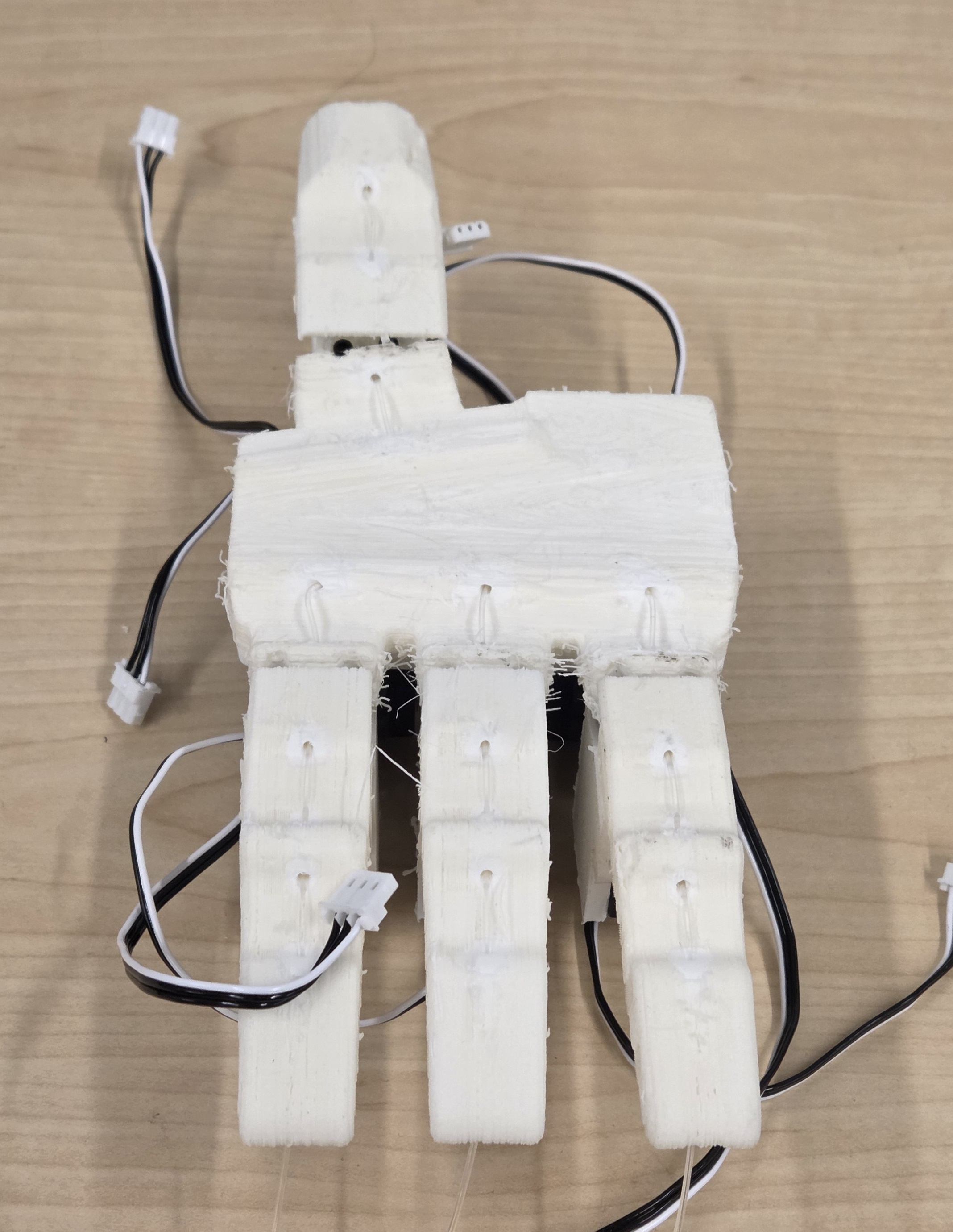
Fingers
Route Tendon Through Finger
- Locate the three channels within the finger and carefully guide the tendon through each channel one at a time.
- Pull the tendon to remove slack, this should probably leave only two to three wraps around the pulley. Tie a regular knot to secure it, then trim any excess for a clean finish.
Attach Finger to Motor
- Use two M2x8mm screws to fasten to the underside of the finger and the side plate to MCP-side motor.
Mounting and Electronics
You can either use the GUI that Feetech provides or my python ID script called set_motor_id.py.
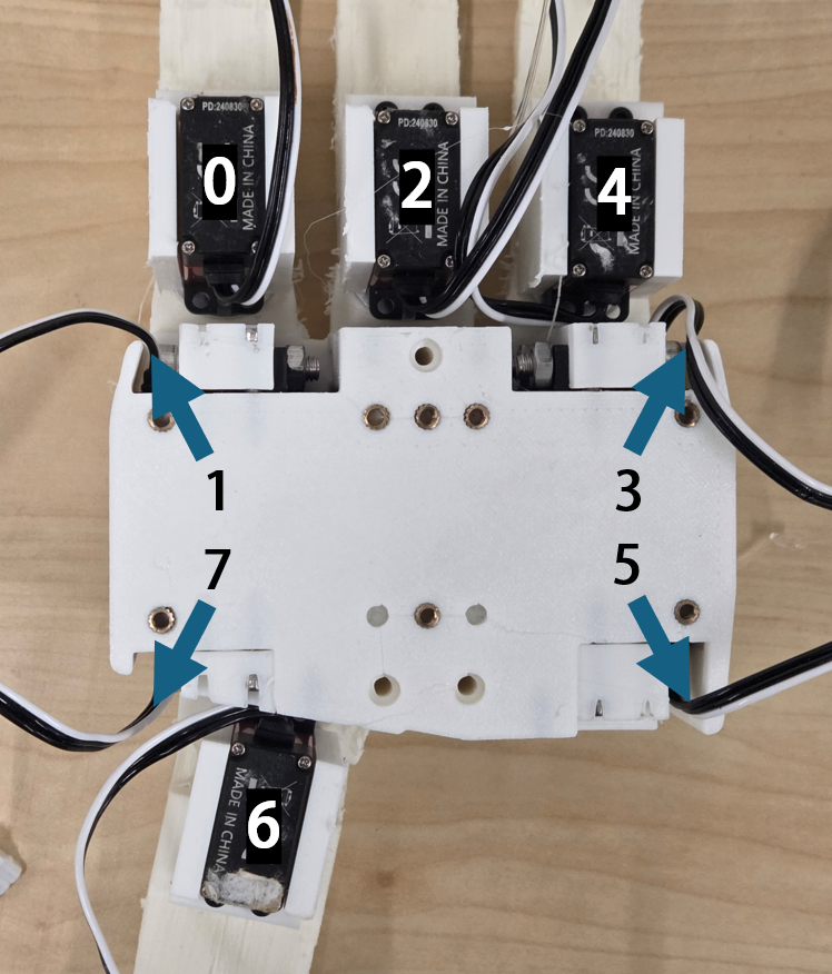
Follow the IDs below:
| ID | MCP Side | Curl |
|---|---|---|
| Index | 0 | 1 |
| Middle | 2 | 3 |
| Ring | 4 | 5 |
| Thumb | 6 | 7 |
- There are 8 open holes around the perimeter of the palm.
- Select 4 evenly spaced holes to attach the lower cover using M2.5 10mm screws.
- Leave the remaining holes unscrewed so they can be used later for attaching the arm mounts.
- Tighten the screws gently—just enough to hold the cover in place and allow the components to align naturally.
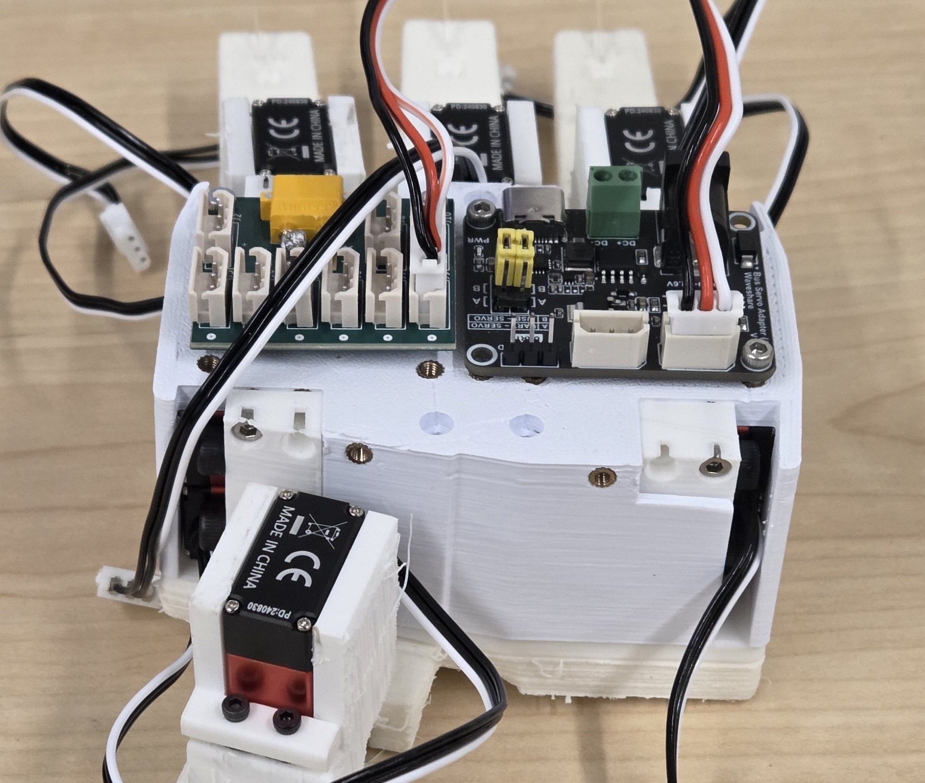
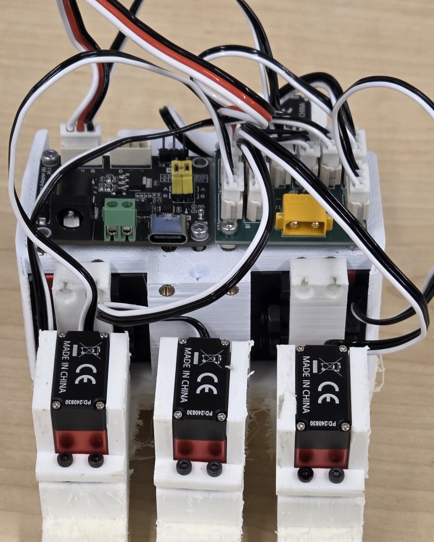
Feetech motors are bus-based servos, meaning each motor has a unique ID and they all share a common wiring system (the bus). The connectors on the back of the motors are identical, and the motors are interconnected via these connectors. You have two options here:
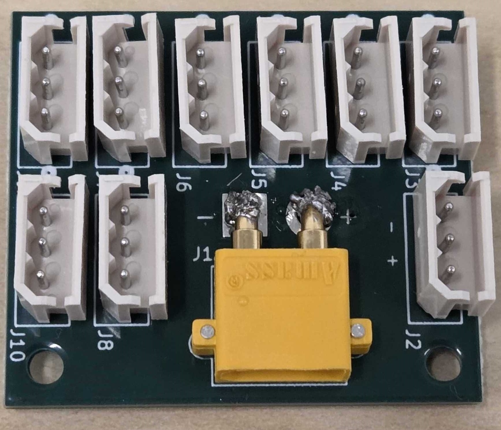
- The LEAP Power Board simplifies the wiring and ensures consistency. You will connect all of the motors to the power board and one Feetech cable to the USB board. The XT30 power will be split by the Power board.
- Use the splitters provided with the motors, chain them all together so they are all connected and wrap the cables into the respective mount of the hand which you will attach below.
I recommend having your chosen mount on hand during the wiring process. This ensures you can properly route and tuck the cables into their designated spots before fully securing the mount to the hand.
Top Mount:
- Make sure the electronics are fastened to the top of the hand.
- Attach the top mount to your robot arm of choice. You will need either M6 or M3 screws of varying lengths depending on your arm.
- Tuck the wires into the top mount and attach the top mount onto the hand. You will need up to 4x M2.5 14mm screws and 4x 8mm screws, but you do not need to use all the screw holes.
- You can use any of the ziptie channels in the four corners of the palm to assist with cable managing the power and usb cables.
Tip: Make sure the MCP side motor cables can move freely once either mount is placed on.
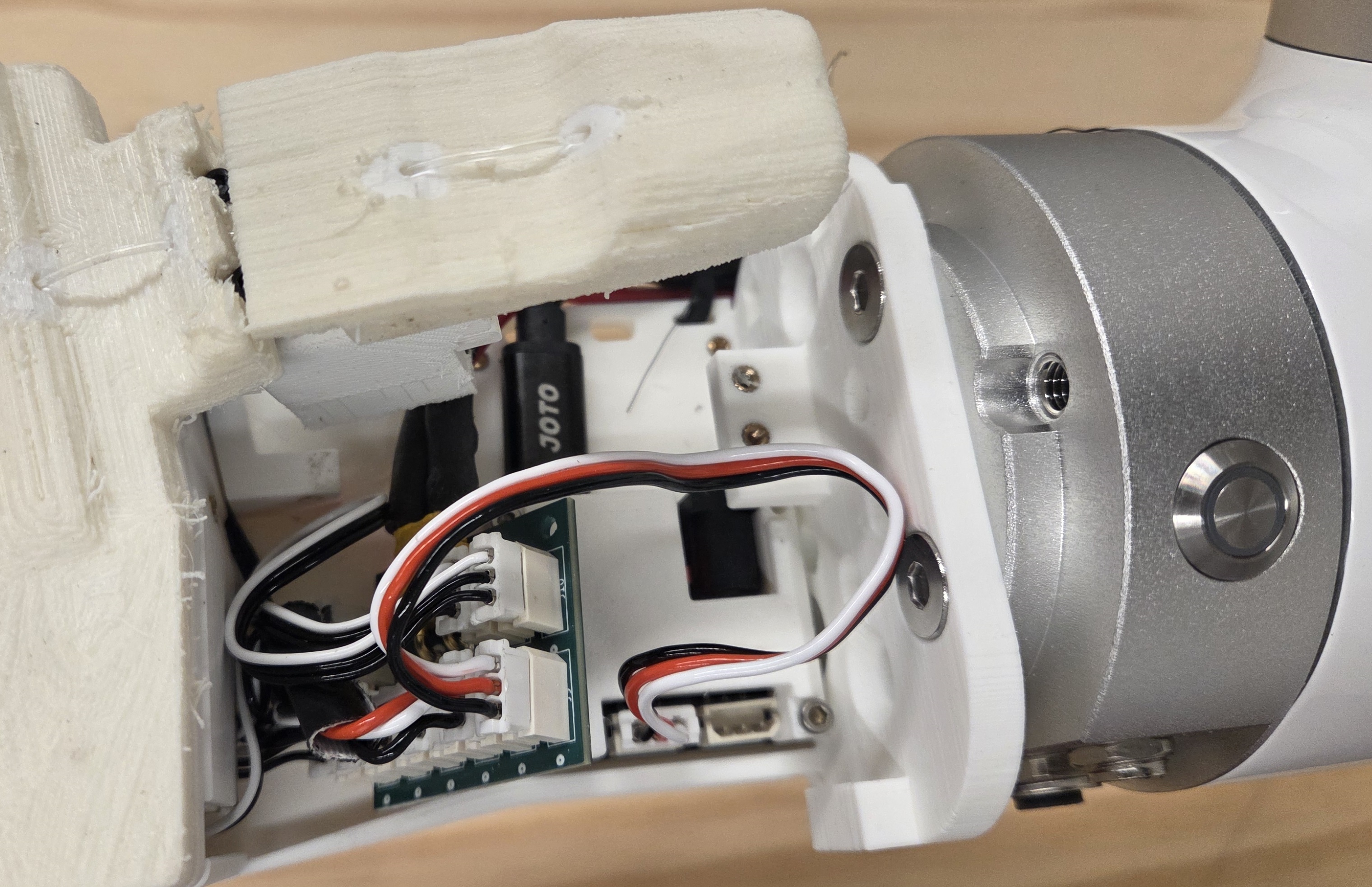
Wrist Mount:
- Secure the wrist mount to the bottom of the hand using M2.5 14mm screws. Ensure all cables are routed through the bottom side of the hand and into the flat part of the wrist mount where the electronics will go.
- Connect the servo cables using either the LEAP Power board or splitters. When using LEAP Power, plug the shorter cables into the ports nearest to the palm so that the MCP side motor cables are not pulled when the MCP curls.
- Slide the USB board beneath its cover and fasten it to the palm using 2 or 3 M2.5 8mm screws. If you are using LEAP Power, it should gently rest on top of the USB board cover. Otherwise you may have to put the USB board under the thumb to make more room for cables.
- Attach the mount to your robot arm of choice. You will need either M6 or M3 screws of varying lengths depending on your arm.
- Align the wrist cover and position it over the motor cables and USB board. You can use two M2.5 8mm screws on the side, two M2.5 8mm screws from the top and one M2.5 6mm screw on the inner screw onto the wrist mount.
- Finally, add one M2.5 16mm screw for the Wrist Lid to the palm cover.
- Attach the USB and XT30 power cables. It's recommended to use zip ties through the provided holes to prevent stress on the board connectors and to get the cables out of the way of the thumb.
Tip: Make sure the MCP side motor cables can move freely once either mount is placed on.
Congratulations on completing the assembly of the hand!
When powering on the hand for the first time and running the tensioning script, ensure that the tendons are properly wrapped and seated inside the pulley grooves.
For more details, refer to the LEAP Hand v2 Software API.
Tip: If you are having trouble with the fingers curling, check that the tendons are properly on the pulleys and the knots are tied tightly.